Turbine Meter Nuflo (2) 2b452v
This document was ed by and they confirmed that they have the permission to share it. If you are author or own the copyright of this book, please report to us by using this report form. Report 3l3c15
Overview 3z723u
& View Turbine Meter Nuflo (2) as PDF for free.
More details 2i4a6q
- Words: 2,843
- Pages: 8
MEASUREMENT SYSTEMS
NUFLO™
Liquid Turbine Flowmeters Accurate Flow Measurement
In 1957, this flowmeter was developed with a tungsten-carbide shaft and bearing to withstand the rugged conditions of the oil field. Over the years, it has earned an unsured reputation for withstanding severe punishment while maintaining operational and measurement integrity. Today, it remains a bestseller among Cameron’s NUFLO liquid measurement products. NUFLO turbine flowmeters indicate flow rate and measure total throughput of a liquid line. As liquid flows through the meter and over the rotor, the rotor turns at a speed that is directly proportional to the flow rate. A magnetic pickup senses the rotor blades as they and generates an electrical (sine wave) signal. These electrical pulses are then transmitted to the flow measurement readout equipment.
Benefits Accurate and repeatable measurement An economical solution for turbine flowmeter applications Easy installation and a variety of end connections Minimum maintenance required Long service life even in severe applications
First Class Design Delivers First Class Performance
4
3
2
2
5
1
6
8
7
1. Permanent 1-in. MNPT conduit connection is standard. 2. ROTOR is pitched and pre-calibrated to determine accuracy. 3. END CONNECTIONS available: flanged, threaded, grooved, EZ-IN®, and WECO® 1502. 4. FLOW VANES increase performance at low rates. 5. FLOW VANE HUB s rotor assembly.
6. ROTOR SHAFT, BEARINGS, AND THRUST BALL are made of tungsten carbide for long service without lubrication other than by the process liquid. 7. RETAINING RINGS make disassembly easy. 8. FLOWMETER BODY is sturdy, one-piece construction, precision finished.
Applications
Accuracy
Cameron offers turbine flowmeters in a variety of end connections and accuracy levels. Typical applications are: • Water-injection measurement • Heater treaters • Test and production separators • Disposal wells • CO2 injection • Steam generator fuel and feed water • Metering liquid fertilizer • Water, fuel, and chemical measurement in plant settings • Chemical tank loading and unloading • Measuring liquid propane • Insitu mining and leaching
Cameron offers two meter grades to satisfy various linearity requirements. The Standard Grade meter is a cost-effective solution for applications equiring accuracy of 1% or less. For higher accuracy, an Industrial Grade meter can be used. Still greater accuracy may be achieved if the expected flow range is specified. Meter Grade
Linearity
Repeatability
Standard*
± 1% of reading
± 0.05%
Industrial*
± 0.5% of reading
± 0.02%
Enhanced accuracy
Consult factory
Consult factory
* For 3/8 in. meters, linearity is ± 2% of reading (standard) and ± 1% of reading (industrial).
MEASUREMENT SYSTEMS
Temperature Range (magnetic pickup) Temperature Range
Meter Size Selection
Flowmeter Size
Standard
-67 to 250°F -55 to 107°C -67 to 250°F -55 to 121°C
3/8 in. through 3/4 in. 7/8 in. through 8 in.
Medium
-67 to 450°F -55 to 232°C
all sizes
Note: Consult Cameron's Measurement Systems division for any use of turbine flowmeters below -20°F (-29°C) or above 250˚F (121˚C).
Compliances • CSA certified for hazardous areas, Class I, Div. 1, Groups A, B, C, D • Meters with maximum working pressures below 7500 psi are compliant with ANSI 12.27.01-2003 Single Seal • EZ-IN meters and WECO 1502 union meters available with CE mark for Pressure Equipment Directive (PED, 97/23/EC)
Materials of Construction • • • • •
Meter Body (Standard) Meter Body (High Pressure) Vanes Rotor Shaft & Bearings
Grade 316L stainless steel* A286 stainless steel* Grade 316L stainless steel CD-4MCu Tungsten carbide
* Traceability of pressure-containing components available on request.
Optional Materials Shaft
Binderless carbide for enhanced corrosion resistance to selected chemicals.
Flowmeter size selection should be based on the instantaneous flow rate of the line into which the meter will be mounted, and on the meter pressure drop. Meter size should never be based on the nominal piping size of the installation. Refer to the Linear Flow Range chart below and the pressure drop curve on page 7 for meter size selection. The meter will remain accurate at flow rates higher than its rating, but over-ranging a meter for long periods can cause excessive bearing wear and pressure drop and shorten the life span of the meter. NUFLO flowmeters can be over-ranged by 10% for short periods without damage.
Installation • The meter should be installed so that the arrow on the meter body corresponds to the flow direction of the line. • A 10-diameter length of straight unrestricted pipe must be upstream and a 5-diameter length of straight unrestricted pipe must be downstream of the flowmeter. Both pipe sections should be the same nominal pipe size as the flowmeter’s end connection. • Throttling/control valves should be located downstream of the flowmeter. Magnetic Pickup/Electronics Installation
• The meter’s permanent conduit connection has 1-in. MNPT threads for attaching an electronic readout instrument. • The conduit connection is designed for use with a 5/8”-18 threaded magnetic pickup, sold separately by Cameron.
Shaft & Bearings
Silver brazing to withstand temperatures to 550˚F and chemicals that attack epoxy bonding bearing materials. Rotor
Nickel plating for enhanced corrosion resistance to selected chemicals (especially acids that corrode ferrous materials).
3
Linear Flow Range (1, 2, 3)
1. 2. 3.
Nominal (2) Calibration Factor
Maximum Output Frequency Pulses/Sec
∅P at Maximum Flow (2)
Flowmeter size (3)
mm
3/8
10
0.3 - 3
0.068 - 0.68
10 - 100
22000
(5812)
1100
4.0
28
3/8
10
0.3 - 3
0.068 - 0.68
10 - 100
22000
(5812)
1100
4.0
28
1/2
13
0.75 - 7.5
0.17 - 1.70
25 - 250
14500
(3830)
1815
12.0
83
3/4
19
2 - 15
0.45 - 3.41
68 - 515
2950
(780)
740
18.0
124
7/8
22
3 - 30
0.68 - 6.81
100 - 1000
2350
(621)
1175
20.0
138
1
25
5 - 50
1.14 - 11.36
170 - 1700
900
(238)
750
20.0
138
GPM
m /HR 3
BPD
Pulses x 1000/m3
Pulses Gallon
psi
kPa
1-1/2
38
15 - 180
3.41 - 40.88
515 - 6000
325
(86)
975
16.0
110
2
51
40 - 400
9.09 - 90.85
1300 - 13000
55
(14.5)
365
22.0
152
3
76
80 - 800
18.16 - 181.66
2750 - 27500
57
(15.2)
760
20.0
138
4
102
100 - 1200
22.71 - 272.55
3400 - 41000
30
(7.9)
600
10.0
69
6
152
250 - 2500
56.78 - 567.82
8600 - 86000
7
(1.8)
290
10.0
6
8
203
350 - 3500
79.49 - 794.94
12000 - 120000
3
(.8)
175
6.0
41
The linear flow range of liquids with non-lubricating characteristics is limited to the upper 60% of rating. Based on water. Consult Cameron's Measurement Systems division for engineering assistance with applications involving liquids of viscosities greater than 5 centistokes on 3/8-in. through 3/4-in. meters.
End Connections NUFLO flowmeters are available in a variety of end connections: • threaded • grooved • flanged • EZ-IN® • WECO® 1502
Threaded (NPT) End Connection • Threaded meter sizes range from 3/8-in. to 2-in. • Meter sizes from 3/8-in. to 1-in. pipe all have 1-in. NPT end connections to simplify meter size changes. • All meter sizes other than the 2-in. have male threads.
4
Flowmeter Size x End Connection Size
Working Pressure psi MPa
in.
Length mm
3/8 x 1 in.
7500
51.7
4.0
102
1/2 x 1 in.
7500
51.7
4.0
102
3/4 x 1 in.
7500
51.7
4.0
102
7/8 x 1 in.
5000
34.5
4.0
102
1 x 1 in.
5000
34.52
4.0
102
1-1/2 x 1-1/2 in.
5000
34.5
6.0
152
1-1/2 x 2 in.
5000
34.5
6.0
152
2 x 2 in.
5000
34.5
10.0
254
3 x 3 in.
1000
6.9
12.5
318
4 x 4 in.
1000
6.9
12.0
305
MEASUREMENT SYSTEMS
Flanged End Connection Turbine flowmeters with flanged end connections are available in both raised-face (RF) models and ring-type t (RTJ) models. Flanged NUFLO meters are constructed with carbon steel or stainless steel slip-on flanges or machined from a single block of stainless steel. Slip-on flanges are welded to the outside of the meter to ensure that the flange never comes into with the process fluid. The flanges are designed to mate with ANSI B16.5 flanges. the factory for availability of materials and construction types for a desired meter size.
Flowmeter Size x End Connection Size
Flange Pressure Rating
in.
Length mm
3/8 x 1/2 in.
150, 300, 600 # 900, 1500, 2500 #
5.0 6.25
127.0 158.8
1/2 x 1/2 in.
150, 300, 600 # 900, 1500, 2500 #
5.0 6.25
127.0 158.8
3/4 x 3/4 in.
150, 300, 600 # 900, 1500, 2500 #
5.0 6.25
127.0 158.8
7/8 x 1 in.
150, 300, 600, 900, 1500, 2500 #
6.0
152.4
1 x 1 in.
150, 300, 600, 900, 1500, 2500 #
6.0
152.4
1-1/2 x 1-1/2 in.
150, 300, 600, 900, 1500, 2500 #
7.0
177.8
2 x 2 in.
150, 300, 600, 900, 1500, 2500 #
8.5
215.9
3 x 3 in.
150, 300, 600, 900 # 1500 # 2500 #
10.0 12.0 15.0
254.0 304.8 381.0
4 x 4 in.
150, 300, 600, 900 # 1500 # 2500 #
12.0 14.0 16.5
304.8 355.6 419.1
6 x 6 in.
150, 300, 600, 900 # 1500 #
12.0 16.0
304.8 406.4
8 x 8 in.*
150, 300, 600, 900 #
12.0
304.8
* factory for other flange classifications above 900 #.
Maximum Working Pressure
Flange
Design-Operating
Pressure Rating
Temperature Range
Flange Material Carbon Steel
Stainless Steel
150 #
-20 to 100˚F -20 to 200˚F -20 to 400˚F -20 to 450˚F
(-28.8 to 37.7˚C) (-28.8 to 93.3˚C) (-28.8 to 204.4˚C) (-28.8 to 232˚C)
285 psi 260 psi 200 psi 185 psi
1.96 mPa 1.79 mPa 1.38 mPa 1.28 mPa
275 psi 235 psi 195 psi 183 psi
1.89 mPa 1.62 mPa 1.34 mPa 1.26 mPa
300 #
-20 to 100˚F -20 to 200˚F -20 to 400˚F -20 to 450˚F
(-28.8 to 37.7˚C) (-28.8 to 93.3˚C) (-28.8 to 204.4˚C) (-28.8 to 232˚C)
740 psi 680 psi 635 psi 620 psi
5.10 mPa 4.69 mPa 4.38 mPa 4.27 mPa
720 psi 600 psi 495 psi 480 psi
4.96 mPa 4.14 mPa 3.41 mPa 3.31 mPa
600 #
-20 to 100˚F -20 to 200˚F -20 to 400˚F -20 to 450˚F
(-28.8 to 37.7˚C) (-28.8 to 93.3˚C) (-28.8 to 204.4˚C) (-28.8 to 232˚C)
1480 psi 1360 psi 1265 psi 1235 psi
10.2 mPa 9.38 mPa 8.72 mPa 8.52 mPa
1440 psi 1200 psi 995 psi 963 psi
9.92 mPa 8.27 mPa 6.86 mPa 6.64 mPa
900 #
-20 to 100˚F -20 to 200˚F -20 to 400˚F -20 to 450˚F
(-28.8 to 37.7˚C) (-28.8 to 93.3˚C) (-28.8 to 204.4˚C) (-28.8 to 232˚C)
2220 psi 2035 psi 1900 psi 1855 psi
15.3 mPa 14.0 mPa 13.1 mPa 12.6 mPa
2160 psi 1800 psi 1490 psi 1443 psi
14.9 mPa 12.4 mPa 10.3 mPa 9.95 mPa
1500 #
-20 to 100˚F -20 to 200˚F -20 to 400˚F -20 to 450˚F
(-28.8 to 37.7˚C) (-28.8 to 93.3˚C) (-28.8 to 204.4˚C) (-28.8 to 232˚C)
3705 psi 3395 psi 3170 psi 3093 psi
25.5 mPa 23.4 mPa 21.8 mPa 21.3 mPa
3600 psi 3000 psi 2485 psi 2408 psi
24.8 mPa 20.7 mPa 17.1 mPa 16.6 mPa
2500 #
-20 to 100˚F -20 to 200˚F -20 to 400˚F -20 to 450˚F
(-28.8 to 37.7˚C) (-28.8 to 93.3˚C) (-28.8 to 204.4˚C) (-28.8 to 232˚C)
6170 psi 5655 psi 5280 psi 5153 psi
42.5 mPa 39.0 mPa 36.4 mPa 35.5 mPa
6000 psi 5000 psi 4140 psi 4010 psi
41.3 mPa 34.5 mPa 28.5 mPa 27.6 mPa
Test Pressure: 1.5 times maximum working pressure at -20 to 100˚ F (-28.8 to 37.7˚ C)
5
Grooved End Connection
WECO® 1502 Union End Connection
Flowmeters with grooved end connections are available in 7/8-in. through 8-in. sizes.
Flowmeters with WECO 1502 end connections are commonly used in high-pressure oilwell service applications. Meter sizes 1”, 1-1/2” and 2” have 2” union end connections with a wing nut on one end and threads on the other end. The 3" meters have 3" union end connections with the option of a wing nut on one end and threads on the other, or threads on both ends. All WECO 1502 union end connection meters have two pickup adapters.
Flowmeter Size x End Connection Size
in.
Length mm
7/8 x 1 in.
4.0
102
1000
6.9
1 x 1 in.
4.0
102
1000
6.9
1-1/2 x 1-1/2 in.
6.0
152
1000
6.9
1-1/2 x 2 in.
6.0
152
1000
6.9
1-1/2 x 2 in.
6.0
152
2500
17.2
2 x 2-1/2 in.
10.0
254
1000
6.9
3 x 3 in.
12.5
318
1000
6.9
1 x 2 in.
8.00
203.3
15000
103
4 x 4 in.
12.0
305
1000
6.9
1-1/2 x 2 in.
8.60
218.4
15000
103
6 x 6 in.
12.0
305
800
5.5
2 x 2 in.
9.00
228.6
15000
103
8 x 8 in.
12.0
305
800
5.5
3 x 3 in.
13.0
330.2
15000
103
6 in.
8 in.
––
––
EZ-IN® End Connection EZ-IN Series turbine flowmeters provide a cost-effective alternative to typical flanged meters. They offer the accuracy, rugged construction, and maintenance-free operation of conventional NUFLO flowmeters plus the following advantages: • Lower installation cost. • Less expensive than a conventional, flanged meter. • Easy installation, removal, and inspection. • Mates to any raised-face flange rated ANSI 150# to 1500#. • Mates to any ring t flange rated ANSI 900#, 1500# or 2500#.
Specialized Flowmeters • • • • • •
High pressure Nitrogen CO2 Cement slurry Corrosive service Drilling fluids
Cameron's Measurement Systems division for application assistance.
6
Working Pressure psi MPa
Flowmeter Size x End Connection Size
in.
Length mm
Working Pressure psi MPa
Meters for use with Raised Face Flanges* Flowmeter Size x End Connection Size
1 in.
2 in.
Lengths, in. (mm) 3 in. 4 in.
3/8 x 1 in.
4.0 (102)
––
3/8 x 2 in.
––
2.5 (63.5)
––
––
––
––
1/2 x 1 in.
4.0 (102)
––
––
––
––
––
1/2 x 2 in.
––
2.5 (63.5)
––
––
––
––
3/4 x 1 in.
4.0 (102)
––
––
––
––
––
3/4 x 2 in.
––
2.5 (63.5)
––
––
––
––
7/8 x 1 in.
4.0 (102)
––
––
––
––
––
7/8 x 2 in.
––
2.5 (63.5)
––
––
––
––
1 x 1 in.
4.0 (102)
––
––
––
––
––
––
––
1 x 2 in.
––
2.5 (63.5)
––
––
––
––
1-1/2 x 2 in.
––
2.5 (63.5)
––
––
––
––
2 x 2 in.
––
2.5 (63.5)
––
––
––
––
2 x 3 in.
––
––
4.25 (108)
––
––
––
3 x 3 in.
––
––
4.25 (108)
––
––
––
4 x 4 in.
––
––
––
5.0 (127)
––
––
6 x 6 in.
––
––
––
––
5.75 (146.1)
––
8 x 8 in.**
––
––
––
––
––
6.25 (158.8)
* Specify flange type (raised face or ring t) when ordering. ** CE-marked meter requires special centering rings.
MEASUREMENT SYSTEMS
Meters for use with Ring t Flanges* Flowmeter Size x End Connection Size
1 in.
2 in.
Lengths, in. (mm) 3 in. 4 in.
6 in.
8 in.
1 x 2 in.
––
3.5 (88.9)
––
––
––
––
1-1/2 x 2 in.
––
3.5 (88.9)
––
––
––
––
2 x 2 in.
––
3.5 (88.9)
––
––
––
––
3 x 3 in.
––
––
4.25 (108)
––
––
––
4 x 4 in.
––
––
––
5.0 (127)
––
––
6 x 6 in.
––
––
––
––
5.75 (146.1)
––
8 x 8 in.
––
––
––
––
––
6.25 (158.8)
* Specify flange type (raised face or ring t) when ordering.
Pressure Drop Curve for NUFLO Turbine Flowmeters Flow Rate - BPD 30 (206.84)
5
10
50
100
500 1,000
5,000 10,000
50,000 100,000
10 (68.95)
Pressure Drop - PSI (kPa)
5 (34.47)
1 (6.90) 0.5 (3.45)
3/4” 7/8” 1”
2” 1-1/2”
0.1 (.690)
3”
1/2” 4”
0.05 (.345)
6” 3/8”
0.01 (.069)
0.1 (.02)
0.5 (.11)
1 (.23)
5 10 (1.14) (2.27)
50 100 (11.36) (22.71)
8”
500 1000 (113.6) (227.1)
5000 (1136.4)
Flow Rate - GPM (m3/hr) (Fluid is water @ 68˚F)
7
MEASUREMENT SYSTEMS
WECO® is a federally ed trademark of FMC Technologies, Inc.
MEASUREMENT SYSTEMS HOUSTON HEAD OFFICE
281.5 82. 9500
NORTH AMERICA
1.8 00 .65 4 . 3 7 6 0 ms-us @ c-a-m.com
ASIA PACIFIC
+60 3 . 5 5 6 9 . 0501 [email protected]
U S A • C A N A D A • U K • C H I N A • U A E • A L G E R I A • M A L AY S I A • I N D I A • R U S S I A
TUR-LIQ NF00001 1208
© Copyright 2012 Cameron International Corp. All Rights Reserved.
EUROPE, MIDDLE EAST & AFRICA
+ 4 4 . 1 2 4 3.8 2 6 7 4 1 [email protected]
w w w. c - a - m . c o m / f l o
Related Documents g842

Turbine Meter Nuflo (2) 2b452v
November 2019 88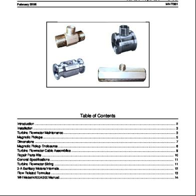
Turbine Meter 5h6j6z
November 2019 86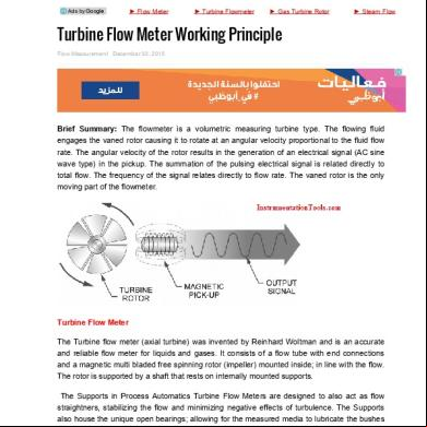
Turbine Flow Meter Working Principle (2) 3w4w4r
November 2019 39
Nuflo 1502 Flow Meter Manual 4at67
October 2019 52
Igtm Gas Turbine Meter Brochure 282s48
October 2019 55
Aga Report 7 Turbine Gas Meter 13555s
October 2019 199More Documents from "Jaime Segura" 3l4z
Turbine Meter Nuflo (2) 2b452v
November 2019 88
Desarrollo Dentario 4z544s
February 2023 0
929
April 2020 12
Subaru Avcs Explicado 6x526c
December 2020 0
Reglamento Departamento Control Comercio De Armas. Copia 3x256s
December 2019 117