2xy33 Polipasto Hoist Dayton 5x435m
This document was ed by and they confirmed that they have the permission to share it. If you are author or own the copyright of this book, please report to us by using this report form. Report 3l3c15
Overview 3z723u
& View 2xy33 Polipasto Hoist Dayton as PDF for free.
More details 2i4a6q
- Words: 3,900
- Pages: 12
Draft7 OIPM 2XY32_33.qxd
5/2/06
10:34 PM
Page 1
2XY32 and 2XY33
Operating Instructions & Parts Manual
Please read and save these instructions. Read carefully before attempting to assemble, install, operate or maintain the product described. Protect yourself and others by observing all safety information. Failure to comply with instructions could result in serious or fatal injury and/or property damage! Retain instructions for future reference.
Dayton Electric Chain Hoists ®
Description
E N G L I S H
Dayton Electric Chain Hoists, Models 2XY32 and 2XY33, are designed for commercial lifting. Use for applications weighing no more than the maximum rated load of hoist. Lift freely suspended (unguided) loads on an intermittent basis only. Not for industrial or production applications requiring continuous operation. Fully inspected and built in accordance with all applicable design and test requirements of OSHA and ANSI for overhead hoists.
Unpacking When unpacking the hoist, inspect for any damage that may have occurred during transit. Check for loose, missing or damaged parts. Do not use this equipment to lift, , or transport people. Do not lift loads over people, or leave a suspended load unattended.
Specifications (Models 2XY32 and 2XY33) Max. rated load..........................1000/2000 lbs. Lifting speed........................................16/8 fpm Max. Lift.....................................................10 ft. HP.............................................................. 2/3HP Power Supply...................115V, 1 phase, 60 Hz
General Safety Information Any person who will be operating or maintaining these hoists should carefully read all information contained herein and in the American National Standard (ANSI) B30.16 Safety Standard for Overhead Hoists. Do not use hoist outdoors or in hazardous locations where explosive gases or particles are present.
ADVERSE ENVIRONMENTAL CONDITIONS DO NOT use in areas containing flammable vapors, liquids, gases or any combustible dusts or fibers. Refer to Article 500 of the National Electrical Code. DO NOT use this hoist in applications involving extended exposure to ambient temperatures below -10F or above 103F.
Form 5S5557
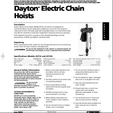
Full load amp draw......................................10A Duty cycle..........................................15 min./hr. PB cord length............................................. 6 ft. Power cord length........................................13" Limit switches............................Upper & Lower
1. Before using hoists operators must be familiar with its controls, operating procedures, and warnings. 2. Test limit switches to be certain they are operating properly. 3. Only use load slings and sling attachments that are properly sized and seated. 4. DO NOT use load chain to wrap around the load or as a sling. 5. Before lifting a load make sure chain is seated in chain wheels or sprockets. 6. Do not use hoist if chain is twisted, kinked, worn or damaged. Printed in China 09667 0506/139/VVP
Figure 1 Min. distance between hooks..18 9/16 "/ 2111/16" Housing height..............................................7" Housing width........................................ 819/32" Housing length.......................................17 7/32 " Hoist weight.......................... 57.30 / 63.92 lbs.
7. Do not use when binding causes an unequal load distribution on the ing chains. 8. Do not attempt to repair a damaged load chain or to lengthen the chain. 9. Use only recommended lubricant when needed. 10. Prevent load chain or hook from with a live welding electrode, weld spatter, or other contaminant. 11. Do not permit chain or hook to be used as a ground when welding. 12. Use hook latches where possible and when using be sure to close the latch.
®
Draft7 OIPM 2XY32_33.qxd
5/2/06
10:34 PM
Page 2
Dayton Operating Instructions and Parts Manual
2XY32 and 2XY33
Dayton Electric Chain Hoists ®
E N G L I S H
General Safety Information (Continued) 13. Do not allow weight of load to rest on hook latch or the tip of the hook. 14. When lifting do not exceed the maximum rated load limit of the hoist. Structural s and load attaching devices must have a load rating equal to or greater than that of the hoist.
15. When moving a load be certain that the pathway is free of any obstructions. 16. Make certain that all persons are warned of an approaching load and that all persons remain clear of a suspended load. Never lift loads over people or leave a load unattended when suspended.
17. When operating hoists always maintain a firm footing and keep your attention focused.
22. Always make repairs or adjustments to damaged or malfunctioning hoists before using. 23. Allow qualified persons only to make repairs or adjustments. 24. Make regular inspections, and keep maintenance records. NOTE: Any damage, malfunction, or unusual change in performance should be reported promptly.
Before beginning a work shift an operator should test the pushbutton station, limit switches and brake control. If not operating properly, they should be replaced or repaired before putting hoist in service.
INSTALLATION OF CHAIN CONTAINER ASSEMBLY See Figures 2A, 2B. 1. Remove screw, nut and washer from the suspension frame (see Fig. 2A).
Installation 1. ing structure and load attaching devices should have a load rating at least equal to that of the selected hoist.
2. Place chain container bracket flush against the suspension frame. Replace washer, nut and screw. Tighten securely (see Fig. 2B).
Hoists must be installed in locations which provide safe operating conditions. Do not use in areas that contain explosive dust, gases, or vapors. Do not use in or near wet areas or outdoors. Make certain that the operator and other persons have room to stand clear of the load at all times.
3. Run load hook down to its lowest position. Place the slack end of the chain in chain container. Feed the remainder of chain into container by operating hoist in the "UP" direction to the top limit. This will permit chain to pile freely and eliminate possibility of jamming which may occur if chain is placed in container by hand.
18. Keep load centered under hoist to avoid any swinging of load.
Avoid use of hoist in areas or applications where slack chain hanging from hoist may create hazardous conditions.
19. If slack occurs, take up carefully. Check load balance and lift a few inches. Then check for load holding action before continuing to lift.
2. The power supply to the hoist should be 115V, single phase, 60 Hz. The voltage can range from plus or minus 10% of 115V.
20. Limit switches should only be used as an emergency device. Do not use for routine stops unless recommended.
3. The hoist is equipped with a 3-prong, grounding plug. Make sure that it is plugged into a properly grounded and installed receptacle.
21. Do not use the loading limiting device to measure a load.
4. After hanging the hoist make sure that the hook latch closes.
2
Suspension Frame
Screw & Nut
Chain Container Assembly Figure 2A
Figure 2B
Draft7 OIPM 2XY32_33.qxd
5/2/06
10:34 PM
Page 3
Dayton Operating Instructions and Parts Manual
Models 2XY32 and 2XY33
General Safety Information (Continued) LIMIT SWITCH OPERATION It is important to check for the proper operation of the limit switches before using the hoist. 1. Press UP button. 2. While hook moves up, raise the limit switch paddle where the chain enters the hoist. 3. Hook should immediately stop. 4. Check DOWN limit switch in similar manner. Do NOT use hoist when brake is not properly working. If hook does not stop within 1 or 2 inches after pushbutton is released, the brake assembly may need to be replaced.
Operation The hoist should be used on an intermittent basis only. Total usage per hour should not exceed fifteen minutes. A thermal cut-off protects the motor from overheating and will also automatically reset it once the motor has sufficiently cooled, so that its operation can be resumed. 1. The hoist should be positioned directly over load. Do NOT attempt to side pull. 2. Hoist chain should not be wrapped around load. Use proper slings. 3. Engage hook with load. Before lifting load make sure load is seated properly.
4. After lifting load clear of its s, stop to check braking action. 5. Avoid jogging the controls or making quick reversals when lifting or lowering a load. 6. Do not use the limit switch for routine stops during normal operation. It should be used as an emergency device. 7. Stand away from load at all times.
Maintenance
any significant repairs or any operating occurrence leading one to suspect that the hoist's capacity may have been impaired. Make certain load is removed from hoist before attempting to service. Also, before attempting to service or remove any components, make certain power supply is disconnected. If power disconnect point is out of sight, lock it in the open position and tag to prevent any unexpected application of power. Only a qualified electrician or service person should perform any electrical troubleshooting or maintenance.
INSPECTION Inspection procedures are listed under three general classifications based upon intervals at which inspection should be performed – daily, quarterly, and annually. Deficiencies should be carefully examined and corrected. The intervals between inspections can vary due to conditions. If the hoist is used under adverse conditions, it should be inspected more often. A planned inspection routine should be established for this hoist based upon frequency, severity of use, and environmental condition. (Reference ASME Standard B30.16). Some inspections should be made frequently (daily to monthly) and others periodically (monthly to yearly). It is strongly recommended that an inspection and Maintenance Check List and an Inspector's Report, similar to those shown in Fig. 6A and 6B, be used and filed for reference. All inspections should be performed or overseen by a designated inspector. Special inspections should be made following
DAILY INSPECTION 1. Inspect the following items every day before operating hoist: a. Check pushbutton station, brake, and limit switches for proper operation. b. Check hooks for deformities, cracks, or chemical damage. Hooks having more than 1-inch opening at throat (see Fig. 3) should be replaced. c. Inspect hook once daily for cracking, extreme wear or spreading. Replace hooks showing any of these signs. If the throat openings are spread wider than the maximum permissible 15% increase listed in Fig. 3, the hooks have been overstressed and must be replaced. Any hook that is bent or twisted more than 10 degrees from the plane of an unbent hook must also be replaced (see Fig. 3). d. Check for open, bent or damaged hook latches. ®
3
E N G L I S H
Draft7 OIPM 2XY32_33.qxd
5/2/06
10:34 PM
Page 4
Dayton Operating Instructions and Parts Manual
2XY32 and 2XY33
Dayton Electric Chain Hoists ®
E N G L I S H
Maintenance (Continued) e. Check chain for wear or damage. f. Check pushbutton cord and power cord for cuts or other damage.
c. Inspect for worn, corroded, cracked, or distorted parts including pins, bearings, shafts, keys, and gears. d. Inspect ing structure and trolley (if used) for ability to the imposed loads.
Figure 3 — Hook Inspection Hoist Capacity 1000 lbs. 2000 lbs.
"X" Dimension Top Hook Bottom Hook 1 7/64 " 1 7/64" 1 15 /64" 1 15/64"
NOTE: Maximum permissible throat opening of hook with latch fully retracted. QUARTERLY INSPECTION
e. Check for worn brake disc by measuring the brake air gap with a feeler gauge. Brake gap larger than the allowable wear limit may cause chatter or failure to release (see Figure 4).
b. Check for loose nuts, bolts, and screws. c. Inspect for worn, corroded, cracked, or distorted parts. d. Check electrical parts, upper and lower limit switches, and pushbutton station. ANNUAL INSPECTION 3. Inspect the following items every year: a. Check items listed under daily and quarterly inspection. b. Check hooks for cracks by means of a magnetic particle test or other crack detecting test.
3. Check overall wear by selecting an unused length of chain and comparing it to a used length. a. Let unworn chain hang vertically with a light load (about 20 pounds) on it to remove slack. b. Measure outside length of a convenient number of links with large caliper.
NOTE: Do not use near flammable liquids or hazardous materials of any kind.
c. Measure same number of links in used section of chain and calculate difference in numbers.
BRAKE REPAIR
d. If length of worn chain is more than 1-1/2% longer than unused chain – chain should be replaced.
When brake does not operate properly as described in installation section, replace entire brake assembly.
2. Inspect the following every 90 days: a. Check items listed under daily inspection.
wear to the link diameter. If any are worn to less than 0.175", the chain must be replaced.
Keep brake surface and brake lining free of grease.
Check for worn brake disc by measuring the brake air gap with a feeler gauge (see Fig. 5). Brake gap larger than the allowable wear limit may cause chatter or failure to release. CHAIN INSPECTION Chain is to be kept clean and lubricated. Visually check chain every time hoist is used. Hoist must not be operated when chain is twisted or kinked. An important phase of hoist maintenance is chain inspection. Check individual link and check for elongation. 1. Check all links for gouges, nicks, weld spatter, and distortion. 2. Inspect and measure each link for
4
IMPORTANT: Chain is designed specially for use with hoist. Do not substitute any other make or type of chain. Never attempt to weld or splice hoist load chain.
TO REPLACE CHAIN 1. Remove lower hook block and chain and ball (Fig. 7, Ref. No. 17). 2. Line up end to end — new chain with old chain — so link welds match. (Welds toward outside of sheave). 3. Use a piece of string or small wire to tie chains together so ends are exactly 9/32" apart. This enables the chain to smoothly through hoist. 4. Operate enough to pull new chain into hoist. Refit springs (Ref. No. 6), lower hook (Ref. No. 86), and end ball (Ref. No. 59).
Draft7 OIPM 2XY32_33.qxd
5/2/06
10:34 PM
Page 5
Dayton Operating Instructions and Parts Manual
Models 2XY32 and 2XY33
Maintenance (Continued)
E N G L I S H
Control Block 1
2
1
2 Blk
3
4
5
6
7
8
9 10 11 12 13 14 15 16 17 18
3 4 Org
5
6
7
8
9 10 11 12 13 14 15 16 17 18 Yel Yel Blu Blu U1 Wht Wht Blu Wht
Grn Blk
V2
Blk
U2
V1 Motor
Rectifier Blk
Gry
Brake
Blu
Wht Relay Blk
Wht
Brn
Figure 4 — Wiring Diagram
Terminal Connection
115V AC 60Hz
Pendant Control Box
LUBRICATION 1. At assembly the gear housing is adequately lubricated with 1/3 pound of grease. If relubrication becomes necessary, use approximately 3/4 cup of a light semifluid NLGI #1 grease.
Keep brake surface and lining free
Armature
Friction Disc
of grease.
BRAKE CHECKING PROCEDURE 1. Remove load and disconnect all AC input power to the hoist.
2. Apply a small amount of grease to the bore of the idler sheave. (Fig. 7, Ref. No. 4) in the bottom block.
2. Remove brake cover (Fig. 7, Ref. No. 70).
3. Wipe chain clean with a cloth periodically and apply a coat of 90 weight gear oil.
3. Check for worn brake disc by measuring the brake air gap with a feeler gauge (See Figure 5). Brake gap larger than the allowable wear limit may cause chatter or failure to release.
IMPORTANT: Do not use grease.
Air Gap
Maximum Allowable Air Gap: 0.039" Figure 5 — Checking Brake Gap
BRAKE REPAIR When the brake is not operating properly, replace the entire brake assembly (Fig. 7, Ref. No. 69). ®
5
Draft7 OIPM 2XY32_33.qxd
5/2/06
10:34 PM
Page 6
Dayton Operating Instructions and Parts Manual
2XY32 and 2XY33
Dayton Electric Chain Hoists ®
E N G L I S H
Maintenance (Continued) INSPECTION AND MAINTENANCE CHECK LIST ELECTRIC POWERED OVERHEAD CHAIN HOIST Type of hoist ____________________________________________________
Capacity (lbs.) ______________________________________________________________
Location _________________________________________________________
Original Installation Date ___________________________________________________
Manufacturer ___________________________________________________
Manufacturer's Serial No. __________________________________________________
Item
Frequency Of Inspection Frequent Periodic Daily Monthly 1-12 Mo.
Possible Deficiencies Any Deficiency Causing Improper Operation
Operating Controls
*
*
*
Limit Switches
*
*
*
Any deficiency causing improper operation
Brake Mechanism
*
*
*
1. Slippage or excessive drift 2. Glazing, contamination or excessive wear
Hooks
Chain
OK
Action Required
Excessive throat opening 15% bent or twisted more than 10 degrees, damaged hook latch, wear, chemical damage, worn hook bearing *
*
*
Inadequate lubrication. Excessive wear or stretch, cracked, damaged or twisted links, corrosion or foreign substance
Nuts, Bolts
*
Looseness, stripped and damaged threads, corrosion
Sheaves
*
Distortion, cracks and excessive wear
Housings,Load Block
*
Cracks, distortion, excessive wear
Wiring and Terminals
*
Fraying, defective insulation
Nameplates, Decals Warning Labels
*
Missing, damaged or illegible
NOTE: Refer to the Maintenance and Inspection Sections of the Hoist-Maintenance Manual for further details. FREQUENCY OF INSPECTION Frequent – Indicates items requiring inspection daily to monthly. Daily inspections may be performed by the operator if properly designated. Periodic – Indicates items requiring inspection monthly to yearly. Inspections to be performed by or under the direction of a properly designated period. The exact period of inspection will depend on frequency and type of usage. Determination of this period will be based on the 's experience. It is recommended that the begin with a monthly inspection and extend the periods to quarterly, semi-annually or annually based on 's monthly experience. Figure 6A — Recommended Inspection and Maintenance Check List
NOTE: This inspection and maintenance check list is in accordance with our interpretation of the requirements of the Safety Standard for Overhead Hoist ASME B30.16. It is , however, the ultimate responsibility of the employer/ to interpret and adhere to the applicable requirements of this safety standard.
6
Draft7 OIPM 2XY32_33.qxd
5/2/06
10:34 PM
Page 7
Dayton Operating Instructions and Parts Manual
Models 2XY32 and 2XY33
Maintenance (Continued)
E N G L I S H
INSPECTOR'S REPORT Item
Remarks (List Deficiencies and Recommended Action)
Inspector's Signature
Date Inspected
Approved By
Date
Figure 6B — Recommended Inspector's Report
®
7
Draft7 OIPM 2XY32_33.qxd
5/2/06
10:34 PM
Page 8
Dayton Operating Instructions and Parts Manual
2XY32 and 2XY33
Dayton Electric Chain Hoists ®
E N G L I S H
Maintenance (Continued) Troubleshooting Chart Symptom
Possible Cause(s)
Corrective Action
Hoist does not respond to pushbutton
1. Power failure in supply lines
1. Check circuit breakers, switches and connections in power supply lines.
2. Wrong voltage or frequency
2. Check voltage and frequency of power supply against the rating on the nameplate of the hoist.
3. Improper connection in hoist or pushbutton
3. Check all connections at line connectors and on terminal block.
4. Brake does not release
4. Check connections to the solenoid coil. Check for open or short circuit.
5. Faulty hoist reversing or
5. Check coil for open or short circuit. Check all connections in control circuit. Check for burned relay. Replace as needed.
1. Hoist overloaded
1. Reduce load to within rated capacity of hoist.
2. Brake not holding
2. Check brake.
Brake does not hold and load drifts down
Brake worn out or brake contaminated
Replace brake assembly.
Brake chatters
1. Check for greater than allowable air gap
1. Replace brake assembly.
2. If brake still chatters after being replaced check rectifier for proper operation (to be performed by a qualified electrician or service person)
2. Replace rectifier.
1. Hoist overloaded. Overload clutch slipping
1. Reduce load to withing rated capacity of hoist.
2. Low voltage
2. Determine cause of flow voltage and bring up to within plus or minus 10% of the voltage specified on the nameplate of the hoist.
Thermal protector opens due to excessive operation
Reduce number of operating cycles.
Hook does not stop promptly
Lack of proper lifting speed
Hoist turns off after several minutes of operation, but then restarts several minutes later
8
Draft7 OIPM 2XY32_33.qxd
5/2/06
10:35 PM
Page 9
E N G L I S H
®
9
Draft7 OIPM 2XY32_33.qxd
5/2/06
10:36 PM
Page 10
E N G L I S H
10
Draft7 OIPM 2XY32_33.qxd
5/2/06
10:37 PM
Page 11
E N G L I S H
11
Draft7 OIPM 2XY32_33.qxd
5/2/06
10:37 PM
Page 12
Dayton Operating Instructions and Parts Manual
2XY32 and 2XY33
Dayton Electric Chain Hoists ®
E N G L I S H
LIMITED WARRANTY DAYTON ONE-YEAR LIMITED WARRANTY. Dayton® Electric Chain Hoists, Models covered in this manual, are warranted by Dayton Electric Mfg. Co. (Dayton) to the original against defects in workmanship or materials under normal use for one year after date of purchase. Any part which is determined to be defective in material or workmanship and returned to an authorized service location, as Dayton designates, shipping costs prepaid, will be, as the exclusive remedy, repaired or replaced at Dayton’s option. For limited warranty claim procedures, see PROMPT DISPOSITION below. This limited warranty gives purchasers specific legal rights which vary from jurisdiction to jurisdiction. LIMITATION OF LIABILITY. To the extent allowable under applicable law, Dayton’s liability for consequential and incidental damages is expressly disclaimed. Dayton’s liability in all events is limited to and shall not exceed the purchase price paid. WARRANTY DISCLAIMER. Dayton has made a diligent effort to provide product information and illustrate the products in this literature accurately; however, such information and illustrations are for the sole purpose of identification, and do not express or imply a warranty that the products are MERCHANTABLE, or FIT FOR A PARTICULAR PURPOSE, or that the products will necessarily conform to the illustrations or descriptions. Except as provided below, no warranty or affirmation of fact, expressed or implied, other than as stated in the "LIMITED WARRANTY" above is made or authorized by Dayton. PRODUCT SUITABILITY. Many jurisdictions have codes and regulations governing sales, construction, installation, and/or use of products for certain purposes, which may vary from those in neighboring areas. While Dayton attempts to assure that its products comply with such codes, it cannot guarantee compliance, and cannot be responsible for how the product is installed or used. Before purchase and use of a product, review the product applications, and all applicable national and local codes and regulations, and be sure that the product, installation, and use will comply with them. Certain aspects of disclaimers are not applicable to consumer products; e.g., (a) some jurisdictions do not allow the exclusion or limitation of incidental or consequential damages, so the above limitation or exclusion may not apply to you; (b) also, some jurisdictions do not allow a limitation on how long an implied warranty lasts, consequentially the above limitation may not apply to you; and (c) by law, during the period of this Limited Warranty, any implied warranties of implied merchantability or fitness for a particular purpose applicable to consumer products purchased by consumers, may not be excluded or otherwise disclaimed. PROMPT DISPOSITION. Dayton will make a good faith effort for prompt correction or other adjustment with respect to any product which proves to be defective within limited warranty. For any product believed to be defective within limited warranty, first write or call dealer from whom the product was purchased. Dealer will give additional directions. If unable to resolve satisfactorily, write to Dayton at address below, giving dealer’s name, address, date, and number of dealer’s invoice, and describing the nature of the defect. Title and risk of loss to buyer on delivery to common carrier. If product was damaged in transit to you, file claim with carrier. Manufactured for Dayton Electric Mfg. Co., 5959 W. Howard St., Niles, Illinois 60714 U.S.A.
Manufactured for Dayton Electric Mfg. Co. Niles, Illinois 60714 U.S.A.
®
5/2/06
10:34 PM
Page 1
2XY32 and 2XY33
Operating Instructions & Parts Manual
Please read and save these instructions. Read carefully before attempting to assemble, install, operate or maintain the product described. Protect yourself and others by observing all safety information. Failure to comply with instructions could result in serious or fatal injury and/or property damage! Retain instructions for future reference.
Dayton Electric Chain Hoists ®
Description
E N G L I S H
Dayton Electric Chain Hoists, Models 2XY32 and 2XY33, are designed for commercial lifting. Use for applications weighing no more than the maximum rated load of hoist. Lift freely suspended (unguided) loads on an intermittent basis only. Not for industrial or production applications requiring continuous operation. Fully inspected and built in accordance with all applicable design and test requirements of OSHA and ANSI for overhead hoists.
Unpacking When unpacking the hoist, inspect for any damage that may have occurred during transit. Check for loose, missing or damaged parts. Do not use this equipment to lift, , or transport people. Do not lift loads over people, or leave a suspended load unattended.
Specifications (Models 2XY32 and 2XY33) Max. rated load..........................1000/2000 lbs. Lifting speed........................................16/8 fpm Max. Lift.....................................................10 ft. HP.............................................................. 2/3HP Power Supply...................115V, 1 phase, 60 Hz
General Safety Information Any person who will be operating or maintaining these hoists should carefully read all information contained herein and in the American National Standard (ANSI) B30.16 Safety Standard for Overhead Hoists. Do not use hoist outdoors or in hazardous locations where explosive gases or particles are present.
ADVERSE ENVIRONMENTAL CONDITIONS DO NOT use in areas containing flammable vapors, liquids, gases or any combustible dusts or fibers. Refer to Article 500 of the National Electrical Code. DO NOT use this hoist in applications involving extended exposure to ambient temperatures below -10F or above 103F.
Form 5S5557
Full load amp draw......................................10A Duty cycle..........................................15 min./hr. PB cord length............................................. 6 ft. Power cord length........................................13" Limit switches............................Upper & Lower
1. Before using hoists operators must be familiar with its controls, operating procedures, and warnings. 2. Test limit switches to be certain they are operating properly. 3. Only use load slings and sling attachments that are properly sized and seated. 4. DO NOT use load chain to wrap around the load or as a sling. 5. Before lifting a load make sure chain is seated in chain wheels or sprockets. 6. Do not use hoist if chain is twisted, kinked, worn or damaged. Printed in China 09667 0506/139/VVP
Figure 1 Min. distance between hooks..18 9/16 "/ 2111/16" Housing height..............................................7" Housing width........................................ 819/32" Housing length.......................................17 7/32 " Hoist weight.......................... 57.30 / 63.92 lbs.
7. Do not use when binding causes an unequal load distribution on the ing chains. 8. Do not attempt to repair a damaged load chain or to lengthen the chain. 9. Use only recommended lubricant when needed. 10. Prevent load chain or hook from with a live welding electrode, weld spatter, or other contaminant. 11. Do not permit chain or hook to be used as a ground when welding. 12. Use hook latches where possible and when using be sure to close the latch.
®
Draft7 OIPM 2XY32_33.qxd
5/2/06
10:34 PM
Page 2
Dayton Operating Instructions and Parts Manual
2XY32 and 2XY33
Dayton Electric Chain Hoists ®
E N G L I S H
General Safety Information (Continued) 13. Do not allow weight of load to rest on hook latch or the tip of the hook. 14. When lifting do not exceed the maximum rated load limit of the hoist. Structural s and load attaching devices must have a load rating equal to or greater than that of the hoist.
15. When moving a load be certain that the pathway is free of any obstructions. 16. Make certain that all persons are warned of an approaching load and that all persons remain clear of a suspended load. Never lift loads over people or leave a load unattended when suspended.
17. When operating hoists always maintain a firm footing and keep your attention focused.
22. Always make repairs or adjustments to damaged or malfunctioning hoists before using. 23. Allow qualified persons only to make repairs or adjustments. 24. Make regular inspections, and keep maintenance records. NOTE: Any damage, malfunction, or unusual change in performance should be reported promptly.
Before beginning a work shift an operator should test the pushbutton station, limit switches and brake control. If not operating properly, they should be replaced or repaired before putting hoist in service.
INSTALLATION OF CHAIN CONTAINER ASSEMBLY See Figures 2A, 2B. 1. Remove screw, nut and washer from the suspension frame (see Fig. 2A).
Installation 1. ing structure and load attaching devices should have a load rating at least equal to that of the selected hoist.
2. Place chain container bracket flush against the suspension frame. Replace washer, nut and screw. Tighten securely (see Fig. 2B).
Hoists must be installed in locations which provide safe operating conditions. Do not use in areas that contain explosive dust, gases, or vapors. Do not use in or near wet areas or outdoors. Make certain that the operator and other persons have room to stand clear of the load at all times.
3. Run load hook down to its lowest position. Place the slack end of the chain in chain container. Feed the remainder of chain into container by operating hoist in the "UP" direction to the top limit. This will permit chain to pile freely and eliminate possibility of jamming which may occur if chain is placed in container by hand.
18. Keep load centered under hoist to avoid any swinging of load.
Avoid use of hoist in areas or applications where slack chain hanging from hoist may create hazardous conditions.
19. If slack occurs, take up carefully. Check load balance and lift a few inches. Then check for load holding action before continuing to lift.
2. The power supply to the hoist should be 115V, single phase, 60 Hz. The voltage can range from plus or minus 10% of 115V.
20. Limit switches should only be used as an emergency device. Do not use for routine stops unless recommended.
3. The hoist is equipped with a 3-prong, grounding plug. Make sure that it is plugged into a properly grounded and installed receptacle.
21. Do not use the loading limiting device to measure a load.
4. After hanging the hoist make sure that the hook latch closes.
2
Suspension Frame
Screw & Nut
Chain Container Assembly Figure 2A
Figure 2B
Draft7 OIPM 2XY32_33.qxd
5/2/06
10:34 PM
Page 3
Dayton Operating Instructions and Parts Manual
Models 2XY32 and 2XY33
General Safety Information (Continued) LIMIT SWITCH OPERATION It is important to check for the proper operation of the limit switches before using the hoist. 1. Press UP button. 2. While hook moves up, raise the limit switch paddle where the chain enters the hoist. 3. Hook should immediately stop. 4. Check DOWN limit switch in similar manner. Do NOT use hoist when brake is not properly working. If hook does not stop within 1 or 2 inches after pushbutton is released, the brake assembly may need to be replaced.
Operation The hoist should be used on an intermittent basis only. Total usage per hour should not exceed fifteen minutes. A thermal cut-off protects the motor from overheating and will also automatically reset it once the motor has sufficiently cooled, so that its operation can be resumed. 1. The hoist should be positioned directly over load. Do NOT attempt to side pull. 2. Hoist chain should not be wrapped around load. Use proper slings. 3. Engage hook with load. Before lifting load make sure load is seated properly.
4. After lifting load clear of its s, stop to check braking action. 5. Avoid jogging the controls or making quick reversals when lifting or lowering a load. 6. Do not use the limit switch for routine stops during normal operation. It should be used as an emergency device. 7. Stand away from load at all times.
Maintenance
any significant repairs or any operating occurrence leading one to suspect that the hoist's capacity may have been impaired. Make certain load is removed from hoist before attempting to service. Also, before attempting to service or remove any components, make certain power supply is disconnected. If power disconnect point is out of sight, lock it in the open position and tag to prevent any unexpected application of power. Only a qualified electrician or service person should perform any electrical troubleshooting or maintenance.
INSPECTION Inspection procedures are listed under three general classifications based upon intervals at which inspection should be performed – daily, quarterly, and annually. Deficiencies should be carefully examined and corrected. The intervals between inspections can vary due to conditions. If the hoist is used under adverse conditions, it should be inspected more often. A planned inspection routine should be established for this hoist based upon frequency, severity of use, and environmental condition. (Reference ASME Standard B30.16). Some inspections should be made frequently (daily to monthly) and others periodically (monthly to yearly). It is strongly recommended that an inspection and Maintenance Check List and an Inspector's Report, similar to those shown in Fig. 6A and 6B, be used and filed for reference. All inspections should be performed or overseen by a designated inspector. Special inspections should be made following
DAILY INSPECTION 1. Inspect the following items every day before operating hoist: a. Check pushbutton station, brake, and limit switches for proper operation. b. Check hooks for deformities, cracks, or chemical damage. Hooks having more than 1-inch opening at throat (see Fig. 3) should be replaced. c. Inspect hook once daily for cracking, extreme wear or spreading. Replace hooks showing any of these signs. If the throat openings are spread wider than the maximum permissible 15% increase listed in Fig. 3, the hooks have been overstressed and must be replaced. Any hook that is bent or twisted more than 10 degrees from the plane of an unbent hook must also be replaced (see Fig. 3). d. Check for open, bent or damaged hook latches. ®
3
E N G L I S H
Draft7 OIPM 2XY32_33.qxd
5/2/06
10:34 PM
Page 4
Dayton Operating Instructions and Parts Manual
2XY32 and 2XY33
Dayton Electric Chain Hoists ®
E N G L I S H
Maintenance (Continued) e. Check chain for wear or damage. f. Check pushbutton cord and power cord for cuts or other damage.
c. Inspect for worn, corroded, cracked, or distorted parts including pins, bearings, shafts, keys, and gears. d. Inspect ing structure and trolley (if used) for ability to the imposed loads.
Figure 3 — Hook Inspection Hoist Capacity 1000 lbs. 2000 lbs.
"X" Dimension Top Hook Bottom Hook 1 7/64 " 1 7/64" 1 15 /64" 1 15/64"
NOTE: Maximum permissible throat opening of hook with latch fully retracted. QUARTERLY INSPECTION
e. Check for worn brake disc by measuring the brake air gap with a feeler gauge. Brake gap larger than the allowable wear limit may cause chatter or failure to release (see Figure 4).
b. Check for loose nuts, bolts, and screws. c. Inspect for worn, corroded, cracked, or distorted parts. d. Check electrical parts, upper and lower limit switches, and pushbutton station. ANNUAL INSPECTION 3. Inspect the following items every year: a. Check items listed under daily and quarterly inspection. b. Check hooks for cracks by means of a magnetic particle test or other crack detecting test.
3. Check overall wear by selecting an unused length of chain and comparing it to a used length. a. Let unworn chain hang vertically with a light load (about 20 pounds) on it to remove slack. b. Measure outside length of a convenient number of links with large caliper.
NOTE: Do not use near flammable liquids or hazardous materials of any kind.
c. Measure same number of links in used section of chain and calculate difference in numbers.
BRAKE REPAIR
d. If length of worn chain is more than 1-1/2% longer than unused chain – chain should be replaced.
When brake does not operate properly as described in installation section, replace entire brake assembly.
2. Inspect the following every 90 days: a. Check items listed under daily inspection.
wear to the link diameter. If any are worn to less than 0.175", the chain must be replaced.
Keep brake surface and brake lining free of grease.
Check for worn brake disc by measuring the brake air gap with a feeler gauge (see Fig. 5). Brake gap larger than the allowable wear limit may cause chatter or failure to release. CHAIN INSPECTION Chain is to be kept clean and lubricated. Visually check chain every time hoist is used. Hoist must not be operated when chain is twisted or kinked. An important phase of hoist maintenance is chain inspection. Check individual link and check for elongation. 1. Check all links for gouges, nicks, weld spatter, and distortion. 2. Inspect and measure each link for
4
IMPORTANT: Chain is designed specially for use with hoist. Do not substitute any other make or type of chain. Never attempt to weld or splice hoist load chain.
TO REPLACE CHAIN 1. Remove lower hook block and chain and ball (Fig. 7, Ref. No. 17). 2. Line up end to end — new chain with old chain — so link welds match. (Welds toward outside of sheave). 3. Use a piece of string or small wire to tie chains together so ends are exactly 9/32" apart. This enables the chain to smoothly through hoist. 4. Operate enough to pull new chain into hoist. Refit springs (Ref. No. 6), lower hook (Ref. No. 86), and end ball (Ref. No. 59).
Draft7 OIPM 2XY32_33.qxd
5/2/06
10:34 PM
Page 5
Dayton Operating Instructions and Parts Manual
Models 2XY32 and 2XY33
Maintenance (Continued)
E N G L I S H
Control Block 1
2
1
2 Blk
3
4
5
6
7
8
9 10 11 12 13 14 15 16 17 18
3 4 Org
5
6
7
8
9 10 11 12 13 14 15 16 17 18 Yel Yel Blu Blu U1 Wht Wht Blu Wht
Grn Blk
V2
Blk
U2
V1 Motor
Rectifier Blk
Gry
Brake
Blu
Wht Relay Blk
Wht
Brn
Figure 4 — Wiring Diagram
Terminal Connection
115V AC 60Hz
Pendant Control Box
LUBRICATION 1. At assembly the gear housing is adequately lubricated with 1/3 pound of grease. If relubrication becomes necessary, use approximately 3/4 cup of a light semifluid NLGI #1 grease.
Keep brake surface and lining free
Armature
Friction Disc
of grease.
BRAKE CHECKING PROCEDURE 1. Remove load and disconnect all AC input power to the hoist.
2. Apply a small amount of grease to the bore of the idler sheave. (Fig. 7, Ref. No. 4) in the bottom block.
2. Remove brake cover (Fig. 7, Ref. No. 70).
3. Wipe chain clean with a cloth periodically and apply a coat of 90 weight gear oil.
3. Check for worn brake disc by measuring the brake air gap with a feeler gauge (See Figure 5). Brake gap larger than the allowable wear limit may cause chatter or failure to release.
IMPORTANT: Do not use grease.
Air Gap
Maximum Allowable Air Gap: 0.039" Figure 5 — Checking Brake Gap
BRAKE REPAIR When the brake is not operating properly, replace the entire brake assembly (Fig. 7, Ref. No. 69). ®
5
Draft7 OIPM 2XY32_33.qxd
5/2/06
10:34 PM
Page 6
Dayton Operating Instructions and Parts Manual
2XY32 and 2XY33
Dayton Electric Chain Hoists ®
E N G L I S H
Maintenance (Continued) INSPECTION AND MAINTENANCE CHECK LIST ELECTRIC POWERED OVERHEAD CHAIN HOIST Type of hoist ____________________________________________________
Capacity (lbs.) ______________________________________________________________
Location _________________________________________________________
Original Installation Date ___________________________________________________
Manufacturer ___________________________________________________
Manufacturer's Serial No. __________________________________________________
Item
Frequency Of Inspection Frequent Periodic Daily Monthly 1-12 Mo.
Possible Deficiencies Any Deficiency Causing Improper Operation
Operating Controls
*
*
*
Limit Switches
*
*
*
Any deficiency causing improper operation
Brake Mechanism
*
*
*
1. Slippage or excessive drift 2. Glazing, contamination or excessive wear
Hooks
Chain
OK
Action Required
Excessive throat opening 15% bent or twisted more than 10 degrees, damaged hook latch, wear, chemical damage, worn hook bearing *
*
*
Inadequate lubrication. Excessive wear or stretch, cracked, damaged or twisted links, corrosion or foreign substance
Nuts, Bolts
*
Looseness, stripped and damaged threads, corrosion
Sheaves
*
Distortion, cracks and excessive wear
Housings,Load Block
*
Cracks, distortion, excessive wear
Wiring and Terminals
*
Fraying, defective insulation
Nameplates, Decals Warning Labels
*
Missing, damaged or illegible
NOTE: Refer to the Maintenance and Inspection Sections of the Hoist-Maintenance Manual for further details. FREQUENCY OF INSPECTION Frequent – Indicates items requiring inspection daily to monthly. Daily inspections may be performed by the operator if properly designated. Periodic – Indicates items requiring inspection monthly to yearly. Inspections to be performed by or under the direction of a properly designated period. The exact period of inspection will depend on frequency and type of usage. Determination of this period will be based on the 's experience. It is recommended that the begin with a monthly inspection and extend the periods to quarterly, semi-annually or annually based on 's monthly experience. Figure 6A — Recommended Inspection and Maintenance Check List
NOTE: This inspection and maintenance check list is in accordance with our interpretation of the requirements of the Safety Standard for Overhead Hoist ASME B30.16. It is , however, the ultimate responsibility of the employer/ to interpret and adhere to the applicable requirements of this safety standard.
6
Draft7 OIPM 2XY32_33.qxd
5/2/06
10:34 PM
Page 7
Dayton Operating Instructions and Parts Manual
Models 2XY32 and 2XY33
Maintenance (Continued)
E N G L I S H
INSPECTOR'S REPORT Item
Remarks (List Deficiencies and Recommended Action)
Inspector's Signature
Date Inspected
Approved By
Date
Figure 6B — Recommended Inspector's Report
®
7
Draft7 OIPM 2XY32_33.qxd
5/2/06
10:34 PM
Page 8
Dayton Operating Instructions and Parts Manual
2XY32 and 2XY33
Dayton Electric Chain Hoists ®
E N G L I S H
Maintenance (Continued) Troubleshooting Chart Symptom
Possible Cause(s)
Corrective Action
Hoist does not respond to pushbutton
1. Power failure in supply lines
1. Check circuit breakers, switches and connections in power supply lines.
2. Wrong voltage or frequency
2. Check voltage and frequency of power supply against the rating on the nameplate of the hoist.
3. Improper connection in hoist or pushbutton
3. Check all connections at line connectors and on terminal block.
4. Brake does not release
4. Check connections to the solenoid coil. Check for open or short circuit.
5. Faulty hoist reversing or
5. Check coil for open or short circuit. Check all connections in control circuit. Check for burned relay. Replace as needed.
1. Hoist overloaded
1. Reduce load to within rated capacity of hoist.
2. Brake not holding
2. Check brake.
Brake does not hold and load drifts down
Brake worn out or brake contaminated
Replace brake assembly.
Brake chatters
1. Check for greater than allowable air gap
1. Replace brake assembly.
2. If brake still chatters after being replaced check rectifier for proper operation (to be performed by a qualified electrician or service person)
2. Replace rectifier.
1. Hoist overloaded. Overload clutch slipping
1. Reduce load to withing rated capacity of hoist.
2. Low voltage
2. Determine cause of flow voltage and bring up to within plus or minus 10% of the voltage specified on the nameplate of the hoist.
Thermal protector opens due to excessive operation
Reduce number of operating cycles.
Hook does not stop promptly
Lack of proper lifting speed
Hoist turns off after several minutes of operation, but then restarts several minutes later
8
Draft7 OIPM 2XY32_33.qxd
5/2/06
10:35 PM
Page 9
E N G L I S H
®
9
Draft7 OIPM 2XY32_33.qxd
5/2/06
10:36 PM
Page 10
E N G L I S H
10
Draft7 OIPM 2XY32_33.qxd
5/2/06
10:37 PM
Page 11
E N G L I S H
11
Draft7 OIPM 2XY32_33.qxd
5/2/06
10:37 PM
Page 12
Dayton Operating Instructions and Parts Manual
2XY32 and 2XY33
Dayton Electric Chain Hoists ®
E N G L I S H
LIMITED WARRANTY DAYTON ONE-YEAR LIMITED WARRANTY. Dayton® Electric Chain Hoists, Models covered in this manual, are warranted by Dayton Electric Mfg. Co. (Dayton) to the original against defects in workmanship or materials under normal use for one year after date of purchase. Any part which is determined to be defective in material or workmanship and returned to an authorized service location, as Dayton designates, shipping costs prepaid, will be, as the exclusive remedy, repaired or replaced at Dayton’s option. For limited warranty claim procedures, see PROMPT DISPOSITION below. This limited warranty gives purchasers specific legal rights which vary from jurisdiction to jurisdiction. LIMITATION OF LIABILITY. To the extent allowable under applicable law, Dayton’s liability for consequential and incidental damages is expressly disclaimed. Dayton’s liability in all events is limited to and shall not exceed the purchase price paid. WARRANTY DISCLAIMER. Dayton has made a diligent effort to provide product information and illustrate the products in this literature accurately; however, such information and illustrations are for the sole purpose of identification, and do not express or imply a warranty that the products are MERCHANTABLE, or FIT FOR A PARTICULAR PURPOSE, or that the products will necessarily conform to the illustrations or descriptions. Except as provided below, no warranty or affirmation of fact, expressed or implied, other than as stated in the "LIMITED WARRANTY" above is made or authorized by Dayton. PRODUCT SUITABILITY. Many jurisdictions have codes and regulations governing sales, construction, installation, and/or use of products for certain purposes, which may vary from those in neighboring areas. While Dayton attempts to assure that its products comply with such codes, it cannot guarantee compliance, and cannot be responsible for how the product is installed or used. Before purchase and use of a product, review the product applications, and all applicable national and local codes and regulations, and be sure that the product, installation, and use will comply with them. Certain aspects of disclaimers are not applicable to consumer products; e.g., (a) some jurisdictions do not allow the exclusion or limitation of incidental or consequential damages, so the above limitation or exclusion may not apply to you; (b) also, some jurisdictions do not allow a limitation on how long an implied warranty lasts, consequentially the above limitation may not apply to you; and (c) by law, during the period of this Limited Warranty, any implied warranties of implied merchantability or fitness for a particular purpose applicable to consumer products purchased by consumers, may not be excluded or otherwise disclaimed. PROMPT DISPOSITION. Dayton will make a good faith effort for prompt correction or other adjustment with respect to any product which proves to be defective within limited warranty. For any product believed to be defective within limited warranty, first write or call dealer from whom the product was purchased. Dealer will give additional directions. If unable to resolve satisfactorily, write to Dayton at address below, giving dealer’s name, address, date, and number of dealer’s invoice, and describing the nature of the defect. Title and risk of loss to buyer on delivery to common carrier. If product was damaged in transit to you, file claim with carrier. Manufactured for Dayton Electric Mfg. Co., 5959 W. Howard St., Niles, Illinois 60714 U.S.A.
Manufactured for Dayton Electric Mfg. Co. Niles, Illinois 60714 U.S.A.
®
Related Documents g842
2xy33 Polipasto Hoist Dayton 5x435m
November 2022 0
Customer Comparison Of Coffing Hoist Vs Dayton Hoist 3u5t5h
November 2019 54
Polipasto 1b4s3q
November 2019 31
Dayton 112257
November 2022 0
Polipasto Manual b414w
March 2023 0
Polipasto Montajes 53lf
December 2019 34More Documents from "Neto Corleone" 5t4ja
2xy33 Polipasto Hoist Dayton 5x435m
November 2022 0
1 Plan De Area Tec-inf 2017 3as4k
June 2021 0
Motion To Resolve 5i6f9
December 2021 0
Cuestionario De Referencias Laborales 3t3e3s
February 2023 0
Affidavit Of Separation Sample 3ip2s
November 2019 137